Here we list some helpful and detailed information on the understanding and the use of the ImageCombinerWarpy.
Functionality / Important notes
- Any number of images can be combined.
- Images of different types (fluorescence, brightfield), (RGB, nChannel, 8bit, 16bit …) can be combined.
- The channels of brightfield images are added as separate channels, even if the original data format was packed RGB.
- The image format of concatenated images is always ‘Fluorescence’, because all channels are treated as separate channels. (Do not change the image type to Brightfield!).
- The base image is the image of the current viewer.
- Overlay images may or may not be displayed in their own viewer.
- If an overlay image is displayed in its own viewer, the viewer’s channel selection is used to display the overlay image and if the new concatenated image is created.
- The channel selection of overlay images displayed in their own viewer can be changed between the alignment phase and image creation. The channel selection is updated in ImageCombiner by ‘re-choosing’ the overlay images (just press button ‘Choose images from project’ and confirm with ‘OK’).
- If an overlay image is not displayed in its own viewer, all* image channels are added to the concatenated image. (all*: depending on the image type, see below).
- The overlay images are aligned one after the other. Each overlay image has its own (warpy/affine) transformation.
- The new concatenated image is added as a new persistent project entry and displayed directly in the current viewer.
- The base and overlay images can be removed from the project after the concatenated image is created.
- The channel names in the concatenated image are derived from the base and overlay image names and the channel names.
Channel selection
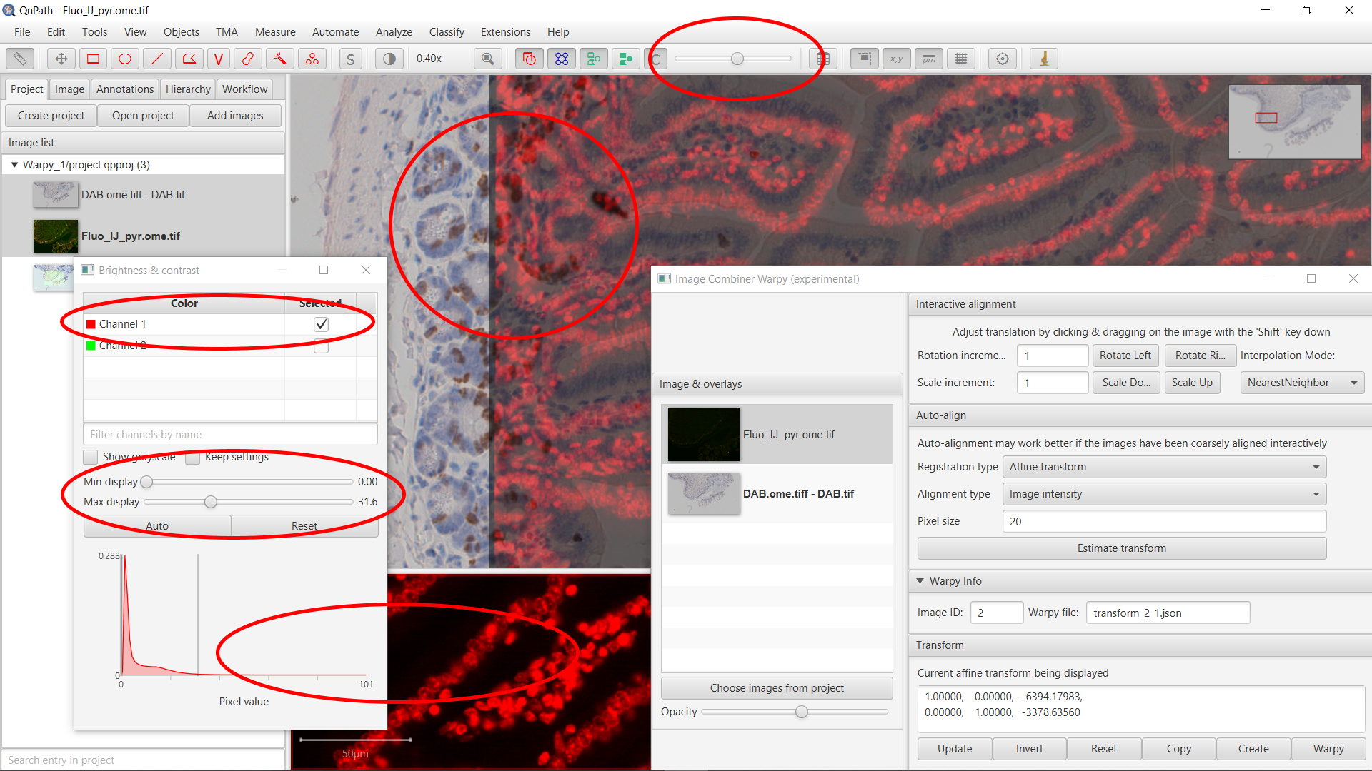
It is possible to combine only certain image channels in the warped image. To do this, adjust the Brightness&Contrast settings as well as the channel selection for all images (base or overlay image) displayed in a separate viewer before using the Warpy command.
Channel selection is also very useful for better display of overlaid images - especially when manually aligning the overlay images. For each image displayed in a separate viewer, the Brightness&Contrast dialog can be called by selecting the viewer. There you can change Min and Max display intensity (and for images of the type Fluorescence the display color). After changing the display parameters, the overlay image can be easily updated by switching the current image selection in the image list in the ImageCombinerWarpy GUI. Very important and helpful is also the setting of the Overlay Opacity by using the slider in the QuPath menu.
Some background information for better understanding:
I) In QuPath brightfield images are handled in a special way. From the RGB channels - the only available channels in the brightfield image data - several additional channels are dynamically generated, i.e. stain channels, ODsum channel, normalized OD channel, hue/saturation/chromaticity channels. These additional channels are not present in the image data itself. If such channels are to be inserted into the concatenated image, they must be ‘regenerated’ by ImageCombiner. Currently, ImageCombiner only supports the ‘regeneration’ of stain channels. (Supporting other channels as well would be possible in principle, but the complexity of the current approach would be overloaded and it would be better to look for an alternative design).
II) If stain channels are added to the concatenated image, only the relevant stain channels are added. This means that for the 2-color brightfield types Brightfield (H-DAB) or Brightfield (H&E), the remaining stain channel (residual channel) is not added to the concatenated image. For the Brightfield (other) image type, all 3 stains are added to the concatenated image.
III) Channel selection in brightfield images is limited to a single channel at a time or a combination of R, G, B channels. Therefore, a decision was required on how to ‘interpret’ brightfield channel selection in ImageCombiner. The details can be found below.
Channel selection in fluorescence images
- In fluorescence images, each channel is already present in the image data. No channel is created dynamically.
- Multiple channel selection is possible in the viewer. The single or multiple channel selection of the viewer is used for overlay display and image concatenation.
- If a fluorescence image is used as an overlay image and is not displayed in a separate viewer, all channels are added to the concatenated image.
Channel selection in brightfield images
In brightfield images, channel selection is more complex for the reason stated above. The following logic is currently used in ImageCombiner to “interpret” channel selection:
- If one or a combination of R, G, B channels is selected, only the selected R, G, B channels are added to the concatenated image.
- If the ‘Original’ channel is selected, the R,G,B channels and all relevant stain channels are added to the concatenated image.
- With any channel selection other than a combination of R, G, B or ‘Original’, only the relevant stain channels are added to the concatenated image. (As mentioned above, ‘relevant’ means 2 stains or 3 stains, depending on the brightfield type.)
- Currently there is no possibility to add only a single stain channel to the concatenated image.
- If a brightfield image is used as an overlay image and is not displayed in a separate viewer, the R,G,B channels and all relevant stain channels are added to the concatenated image (similar to channel selection ‘Original’).
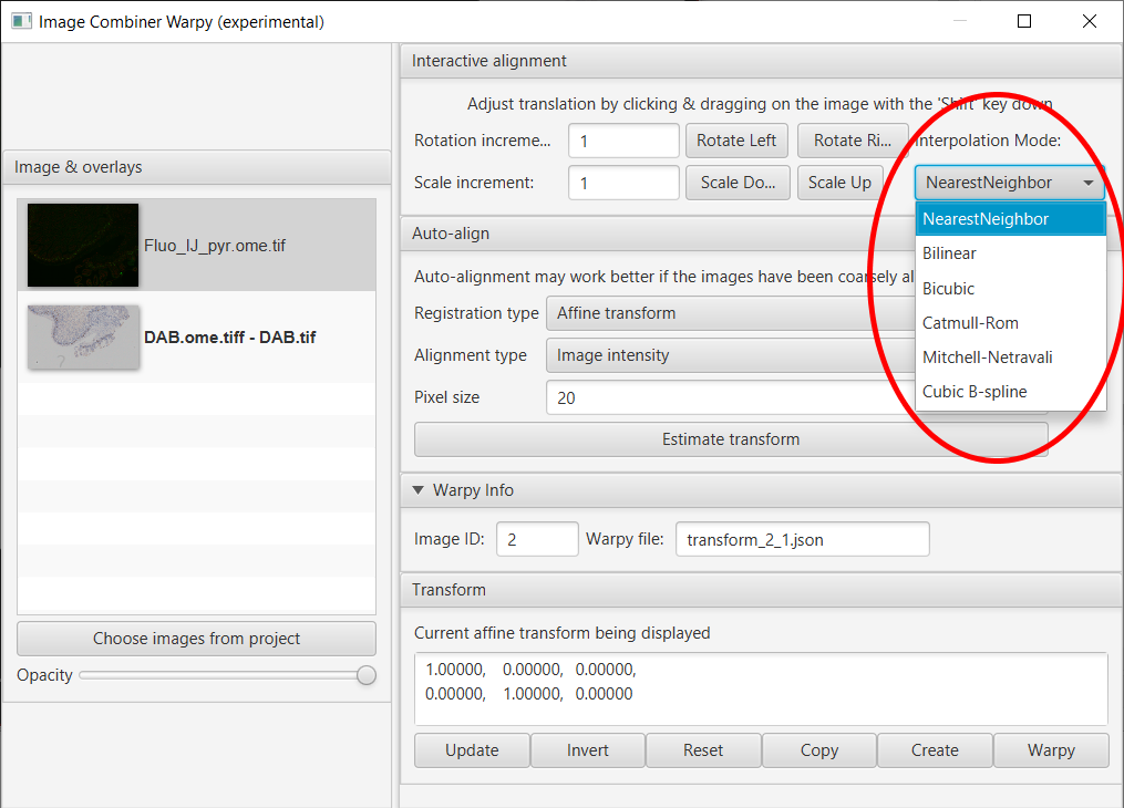
Interpolation
Different methods of pixel interpolation can be used for image overlaying.
Currently the following methods are supported:
- NearestNeighbor
- Bilinear
- Bicubic
- Catmull-Rom
- Mitchell-Netravali
- Cubic B-spline
Pixel interpolation is applied only to the overlay images, not to the base image.
The following image illustrates the influence of different interpolations on the pixel intensities of an overlay image:
W. Burger, M.J. Burge: Digital Image Processing – An Algorithmic Introduction Using Java, Springer, London (2008).
Transformation
Combined images can be created either with a non-linear splice (Warpy) transformation or with a linear affine transformation.
Multiple images can be selected and overlayed. The only condition is that Warpy transformation files exist for all overlay images and that all overlay images have been transformed to the same base image. Otherwise the Warpy button is disabled.
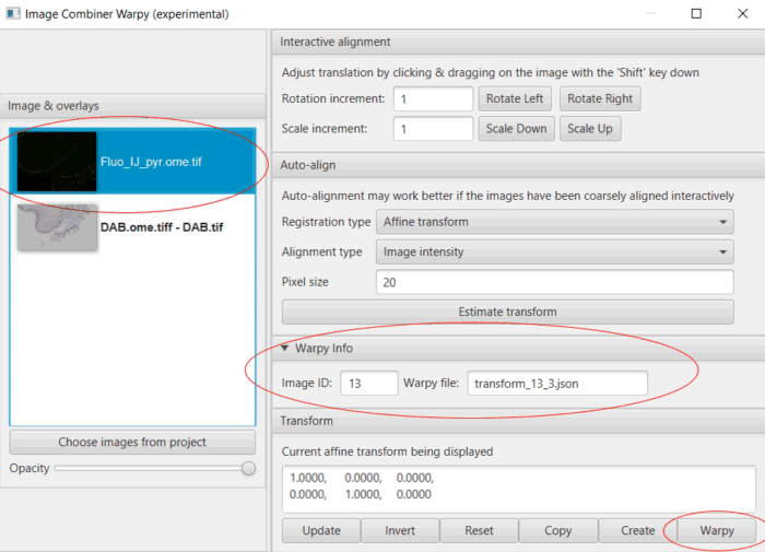
Affine transformation can be used either by manual shifting, scaling and rotating the overlay image in the overlay preview in the current viewer or by using a transformation matrix in the text section.
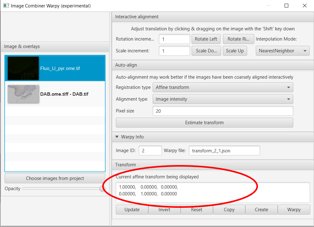
The 2D transformation matrix consists of 6 elements (more info on wikipedia):
\[\begin{bmatrix} m_{11} & m_{12} & m_{13}\\m_{21} & m_{22} & m_{23}\end{bmatrix}\]The sub matrix:
\[\begin{bmatrix} m_{11} & m_{12} \\m_{21} & m_{22} \end{bmatrix}\]specifies the rotation, scaling, shearing, reflection etc.
The sub vector:
\[\begin{bmatrix} m_{13}\\m_{23}\end{bmatrix}\]specifies the translation (in scaled pixel coordinates of the overlay image).
A combination of Affine Transformation and Warpy Transformation is not possible.
Project entry <> image file
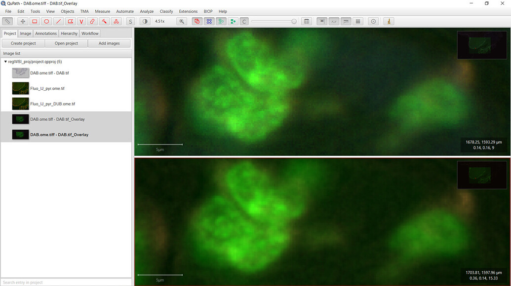
The ImageCombinerWarpy can display/generate superimposed images of different WSI’s in QuPath. The creation of the superimposed images can be very fast, as no new image data needs to be generated.
The superimposed images are derived from existing images files and combined via a special TransformingImageServer class in QuPath. They are accessible via newly created QuPath project entries that contain the links to the original images, spatial transformation/deformation information, and other slide-specific data in Json format. As described in the warning, it is strongly recommended to save the images in a useful format, such as OME TIFF, if a future access of the project/image has to be guaranteed.
The most easy way to save a superimposed image is to use the QuPath function File>Export images...>OME TIFF.
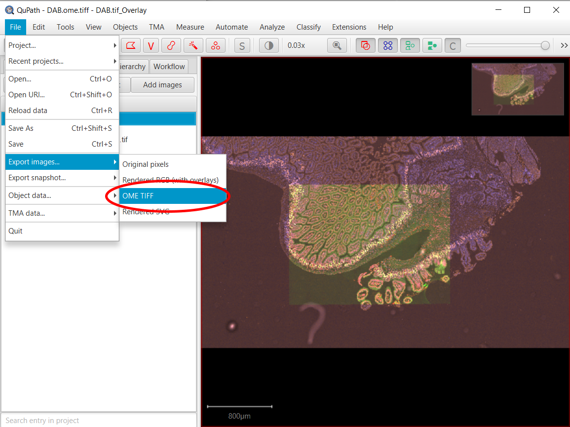
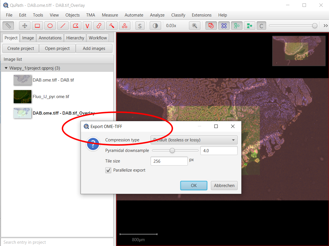
Image export can also be done in batch mode via QuPath scripting or directly with Warpy in Fiji.